
Khephren Gould
University of Victoria
Department of Electrical and Computer Engineering
UVic Rocketry
Currently living in: Victoria, BC, Canada
phone: 236-508-9159
e-mail: khephrengould@gmail.com
GitHub LinkedIn Resume (PDF)
University of Victoria
Department of Electrical and Computer Engineering
UVic Rocketry
Currently living in: Victoria, BC, Canada
phone: 236-508-9159
e-mail: khephrengould@gmail.com
GitHub LinkedIn Resume (PDF)
Anduril 3 Sensor and Data Acquisition System (CAnduril) FPGA-based 16-Bit Harvard Architecture CPU Early Stage Wildfire Detection System Fixed-Point Butterworth Lowpass Filter for the ARM Cortex-A7 Strain Gauge Signal Conditioning System Invoice Manager The Wanderer A2 Camera Clock Radio Autonomous Robot
KiCad, STM32, C, CAN bus, Git
Looking down the airframe. Status LEDs on the DAQ nodes.
A flight data acquisition system for UVic Rocketry's Anduril 3 sounding rocket. Nine sensor nodes distributed around the airframe measure strain, pressure and temperature and report to the flight computer over CAN.
Anduril 3 needed in-flight data good enough to validate the team's CFD model. That meant four measurements: strain at the point of maximum bending, the rocket's airspeed, the pressure gradient over the nosecone, and fuselage surface temperature to calibrate the strain readings against thermal drift. Translated into hardware, the system had to read 12 three-gauge strain rosettes, 4 SPI-output pressure ports and 4 platinum RTDs, and get all of it to the flight computer.
The system is 9 data acquisition nodes distributed around the airframe, reporting to the flight computer over a 1 MHz CAN bus. Each node is a 4-layer mixed-signal PCB carrying an STM32G4, an MCP3562 4-channel 24-bit ADC sampling three strain gauges, the internal ADC reading an RTD at 5 Hz, a TCAN3414 CAN transceiver, and the bridge completion, amplification and anti-alias filtering ahead of them. Firmware is C on FreeRTOS with separate tasks for sensor reading, status LED and CAN transmission, built with arm-none-eabi-gcc and CMake. Gauge placement follows the Skopinski method: 0/45/90 rosettes in four rings of three at 120 degree separation, with one RTD per ring for post-flight temperature calibration. Applying more loads than there are gauges makes the system overdefined, so the coefficients come from a least-squares fit.
An important design decision was how to ground a board carrying microvolt analog signals and high speed digital on the same four layers. The common approach is a split ground plane joined by a net tie, but any signal crossing the split takes a long return path and becomes an EMI target. I used separate analog and digital supply rails over a single shared ground plane instead, then routed so that analog and digital return paths never intersect. The supply choice followed the same logic: Anduril 3's modular power supply is a buck-boost switcher, so I picked an analog regulator with 60 dB PSRR at 100 Hz specifically to keep switching noise off the sensor inputs. Signal chain analysis put the instrumentation amplifier as the dominant noise source, leaving 13.08 effective bits and a strain precision of roughly 5 microstrain.
The flight returned strain data from 7 of 9 gauges and 3 of 4 temperature sensors. The pressure port data was lost when the flight computer hit a stack overflow about 2 minutes into the flight. That fault was reproducible on the bench and did not need a launch to find. The lesson is to test as much as possible before flight, and to include the integrated system in that testing.
Bench test. Strain readings plotting live as the airframe section is loaded by hand.
Final report: Sensors and Data Acquisition. Open the PDF (18 pages).
Pictures (7)
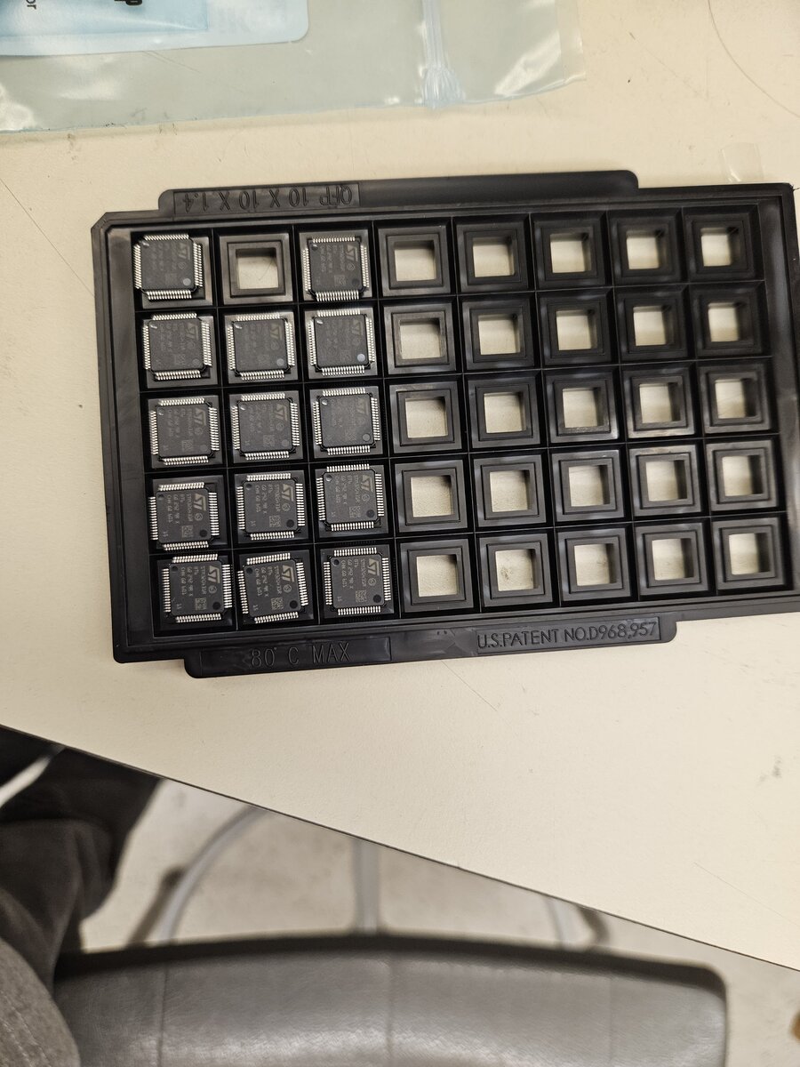 STM32G4 microcontrollers.
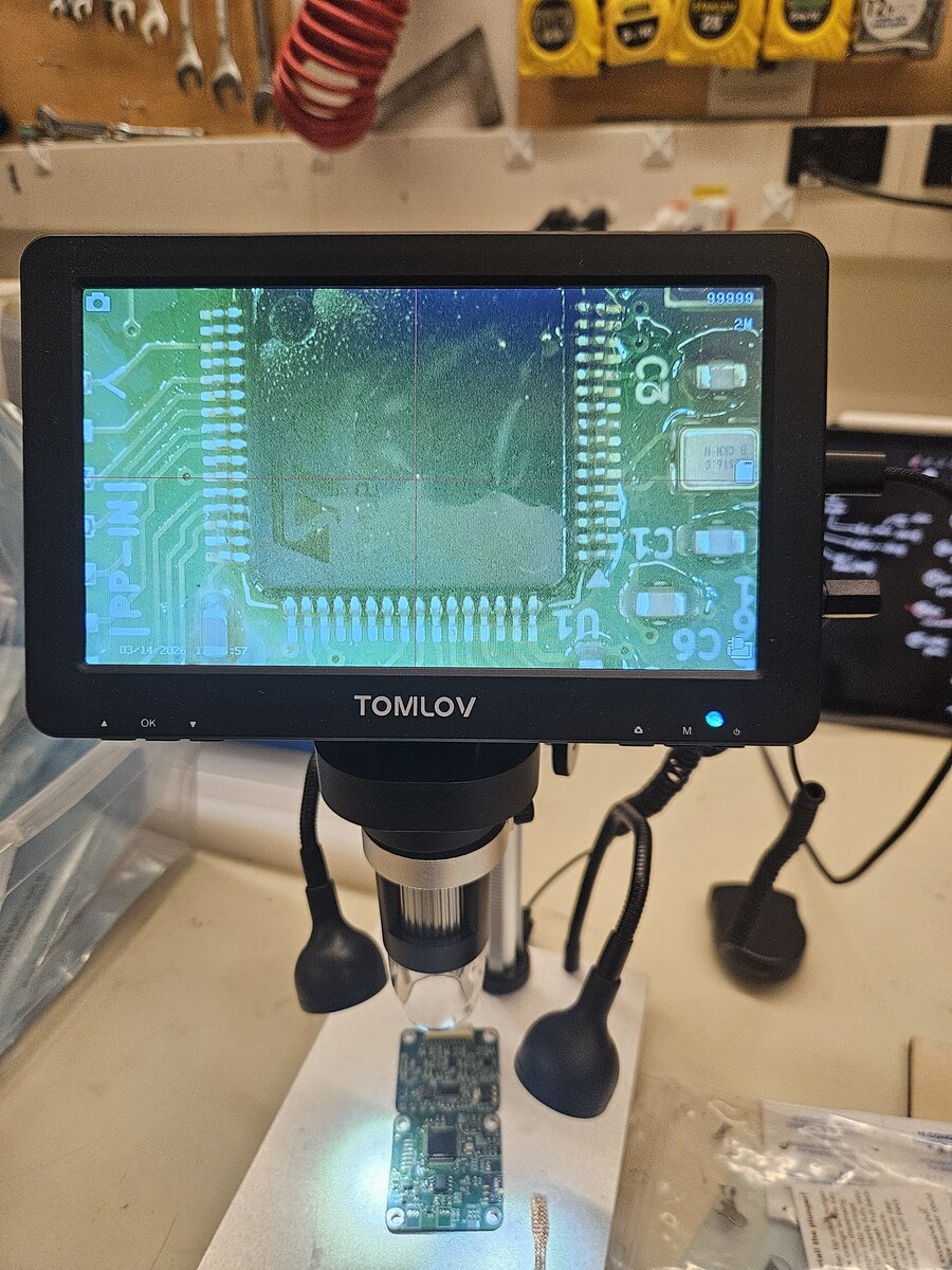 Board inspection under the microscope.
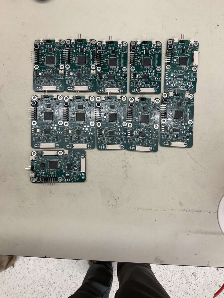 Assembled DAQ nodes.
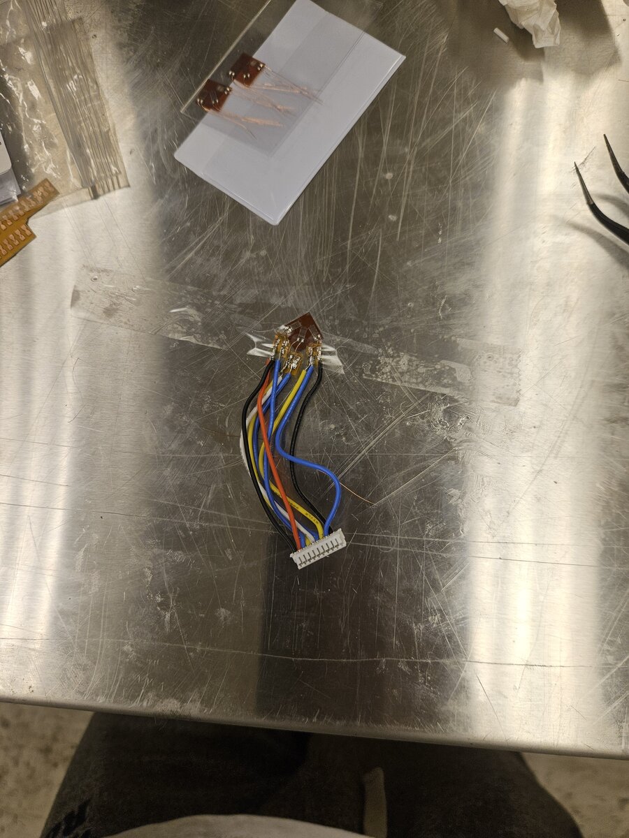 Strain gauge rosette on its JST harness.
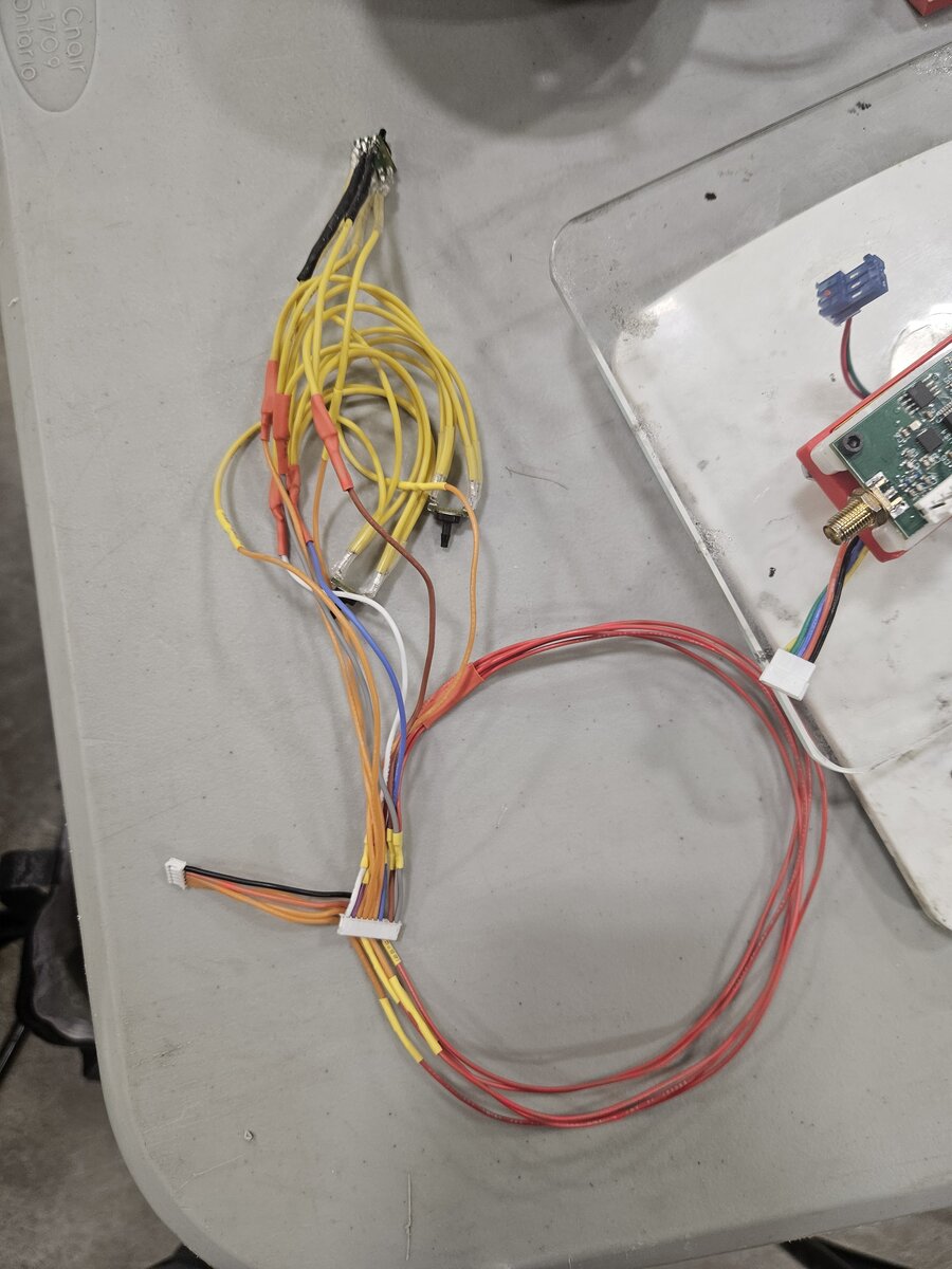 A node wiring harness.
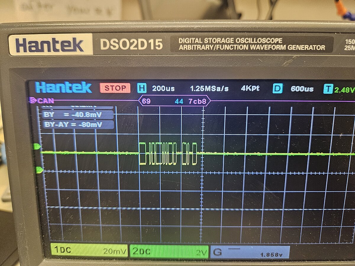 A CAN frame decoded on the bench.
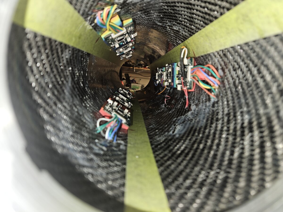 Nodes bonded inside the airframe.
VHDL, Xilinx Vivado, computer architecture, pipelining
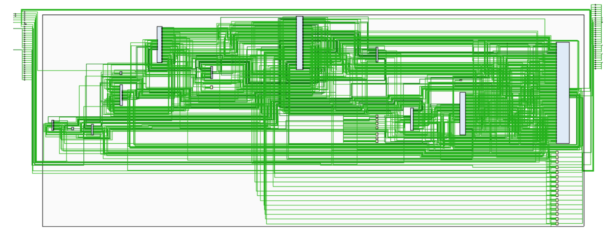
A 16-bit, 5-stage pipelined Harvard architecture processor written in VHDL and implemented on a Xilinx Artix-7 FPGA.
The goal was to design a processor capable of executing any program written in a provided instruction set, synthesize it onto an FPGA, and verify it on hardware. The specification called for a Harvard architecture with a dual-ported RAM separating instruction and data traffic, a 1024-byte ROM at 0x0000 holding a bootloader, a 1024-byte RAM at 0x0800, and memory-mapped I/O with the input port at 0xFFF0 and the output port at 0xFFF2. The ISA is a fixed-width 16-bit encoding in three formats with 8 general-purpose registers and two status flags.
We built it as a 5-stage pipeline in VHDL on a Xilinx Artix-7: fetch, decode, execute, memory access, write back, separated by 48, 115, 42 and 39-bit pipeline registers. The register file has dual read ports, combinational reads and falling-edge writes. Data hazards are handled by a forwarding unit that routes results back from the EX/MEM and MEM/WB stages into the execute inputs, with a separate detection unit stalling and inserting a bubble for the load-use case that cannot be forwarded. Control hazards are handled by flushing IF/ID and ID/EX when a branch is taken. We extended the base ISA with BRR.OVERFLOW, which branches on signed arithmetic overflow, backed by a dedicated V flag in the program status register. Post-synthesis the design uses 1653 LUTs, 532 registers, 247 muxes and a single DSP48E1 block for the multiplier. The critical path runs from the ID/EX register through the combinational multiplier to the V flag, which is clocked on the falling edge so the flag is available in the execute stage where branches resolve, and that halves the slack on that path. Vivado reports positive hold slack throughout, and the processor was verified on hardware up to 100 kHz running a factorial program that exercised arithmetic, conditional branching, memory-mapped I/O and the overflow extension.
An important design decision was resolving data hazards by forwarding instead of stalling. Stalling whenever an instruction reads a register that an earlier instruction has not written yet is simple, but it costs cycles. Following the scheme in Patterson and Hennessy, we built a forwarding unit that compares the destination register in the EX/MEM and MEM/WB pipeline registers against the two source registers in ID/EX, and drives a pair of 2-bit selects on multiplexers at the ALU inputs. A result can then be routed back into the execute stage before it reaches the register file. When EX/MEM and MEM/WB both hold a pending write to the same register, EX/MEM takes priority because it holds the more recent result. Forwarding cannot resolve load-use hazards, since a loaded value is not available until the memory stage. Those are handled by a separate detection unit that disables the PC and the IF/ID register and clears ID/EX to insert a bubble. Together the two gave a 20% speedup across the benchmark programs.
We started with all the control logic in a sequential state machine, which is the wrong model for a pipeline. In a pipelined design the control signals have to travel alongside their instruction inside the pipeline registers, so that every functional unit has the state it needs for whichever instruction is currently in front of it. We also started by building the ALU at the gate level and abandoned that in favour of numeric_std, which made the case for hierarchical design and for leaning on existing libraries instead of rebuilding arithmetic from primitives.
Final report: 16-Bit Pipelined Processor. Open the PDF (44 pages).
A-format instructions (arithmetic, logic, shift, test, I/O)
| Mnemonic | Opcode | Function | Syntax |
|---|---|---|---|
| NOP | 0 | Nothing | NOP |
| ADD | 1 | R[ra] ← R[rb] + R[rc] | ADD ra,rb,rc |
| SUB | 2 | R[ra] ← R[rb] − R[rc] | SUB ra,rb,rc |
| MUL | 3 | R[ra] ← R[rb] × R[rc] | MUL ra,rb,rc |
| NAND | 4 | R[ra] ← R[ra] NAND R[rb] | NAND ra,rb,rc |
| SHL | 5 | Shift R[ra] left by n = cl[3:0] | SHL ra#n |
| SHR | 6 | Shift R[ra] right by n = cl[3:0] | SHR ra#n |
| TEST | 7 | Z ← (R[ra] = 0); N ← (R[ra] < 0) | TEST ra |
| OUT | 32 | OUT.PORT ← R[ra] | OUT ra |
| IN | 33 | R[ra] ← IN.PORT | IN ra |
B-format instructions (branches)
| Mnemonic | Opcode | Function | Syntax |
|---|---|---|---|
| BRR | 64 | PC ← PC + 2 × disp.l | BRR +disp.l |
| BRR.N | 65 | If N = 1, PC ← PC + 2 × disp.l | BRR.N +disp.l |
| BRR.Z | 66 | If Z = 1, PC ← PC + 2 × disp.l | BRR.Z +disp.l |
| BR | 67 | PC ← R[ra] + 2 × disp.s | BR ra+disp.s |
| BR.N | 68 | If N = 1, PC ← R[ra] + 2 × disp.s | BR.N ra+disp.s |
| BR.Z | 69 | If Z = 1, PC ← R[ra] + 2 × disp.s | BR.Z ra+disp.s |
| BR.SUB | 70 | r7 ← PC + 2; PC ← R[ra] + 2 × disp.s | BR.SUB ra+disp.s |
| RETURN | 71 | PC ← r7 | RETURN |
| BRR.OVERFLOW | 72 | If V = 1, PC ← PC + 2 × disp.l. Our extension instruction. | BRR.OVERFLOW +disp.l |
L-format instructions (load, store, move)
| Mnemonic | Opcode | Function | Syntax |
|---|---|---|---|
| LOAD | 16 | R[r.dest] ← M[R[r.src]] | LOAD r.dest, r.src |
| STORE | 17 | M[R[r.dest]] ← R[r.src] | STORE r.dest, r.src |
| LOADIMM | 18 | R7[15:8] or R7[7:0] ← imm | LOADIMM.upper #n |
| MOV | 19 | R[r.dest] ← R[r.src] | MOV dest,src |
Pictures (9)
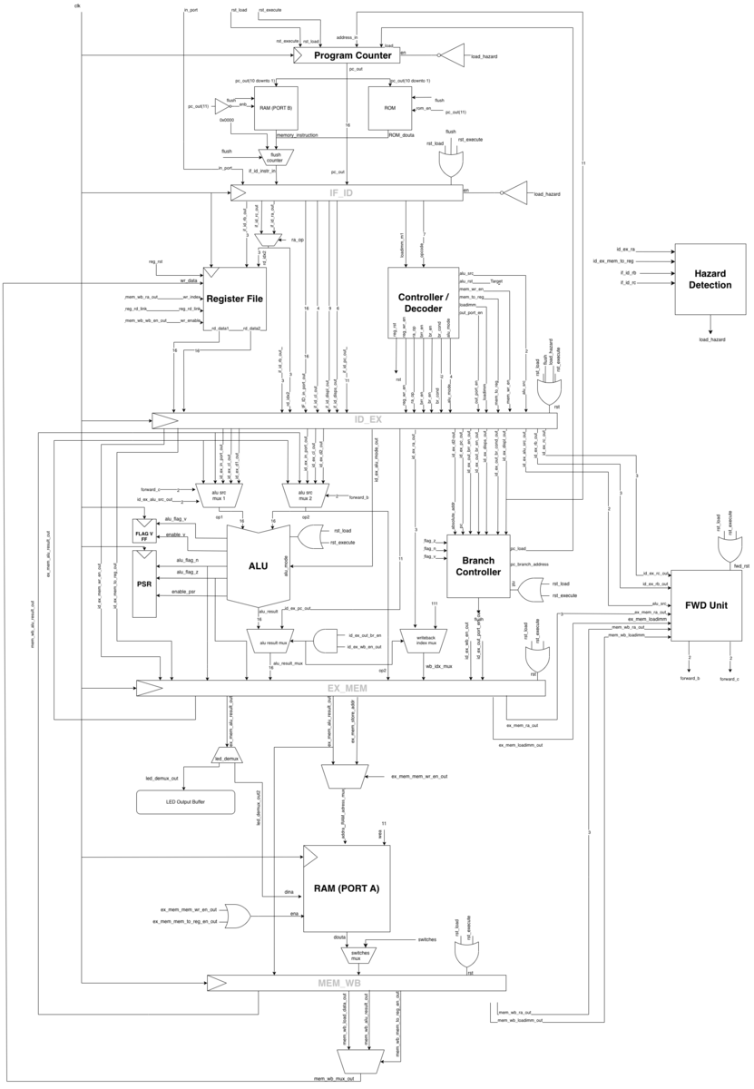 Datapath microarchitecture.
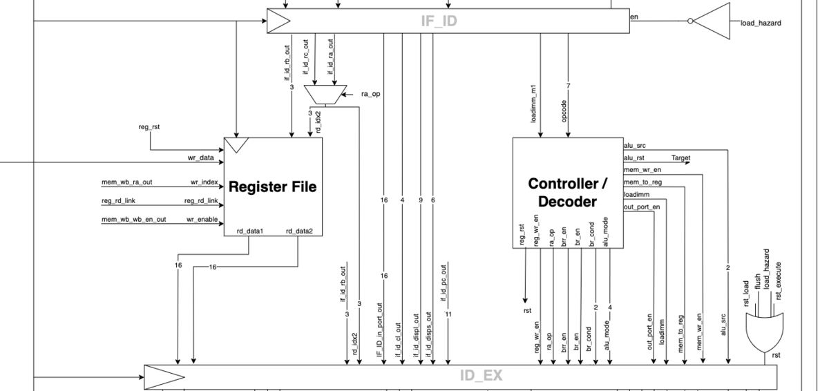 Decode stage.
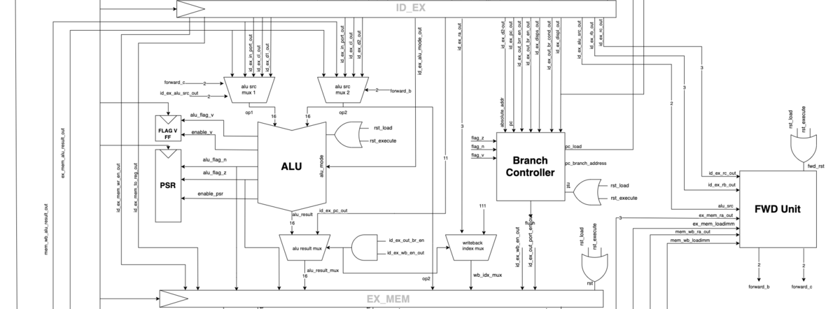 Execute stage.
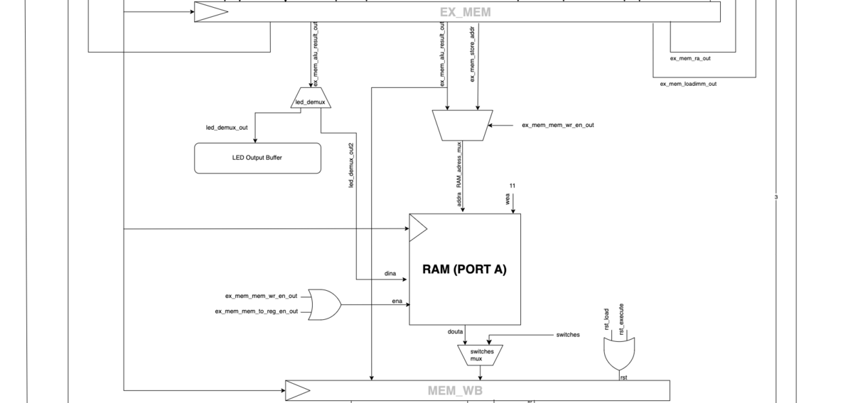 Memory access stage.
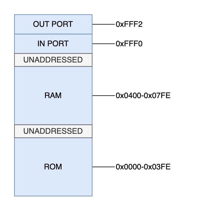 Memory map.
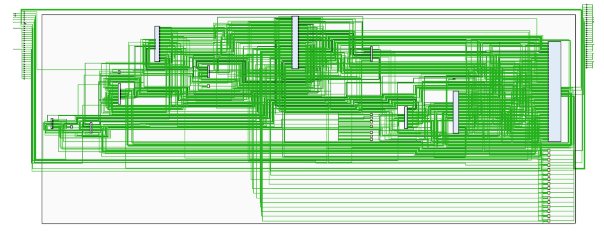 Implementation schematic.
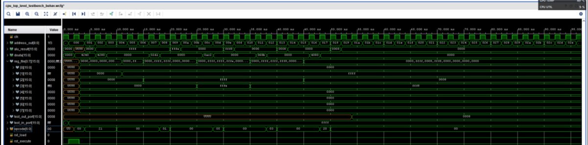 Pipeline simulation waveform.
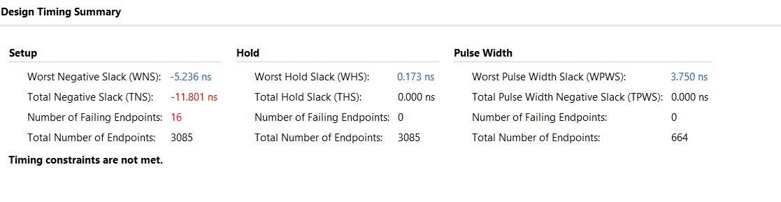 Vivado timing summary.
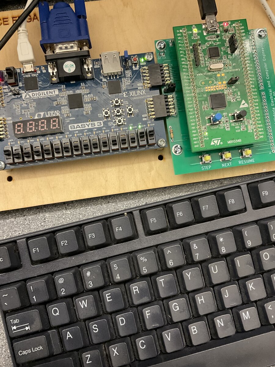 Basys 3 running the CPU, with the bootloader host board.
Engineering design, LTspice, STM32CubeIDE, LoRa
An environmental sensor network for detecting wildfires early, built in a team of three. Solar-powered nodes measure gas, temperature and humidity and report over LoRa to a gateway and a web dashboard.
Most wildfires are contained during the initial response. The ones that escape early containment account for the majority of the damage, and detection time is a large part of what delays that response. Satellite monitoring has a spatial resolution around 5 hectares, which is too coarse to catch a fire while it is still small. We set out to find whether a network of cheap ground sensors could close that gap, and what it would cost to build one.
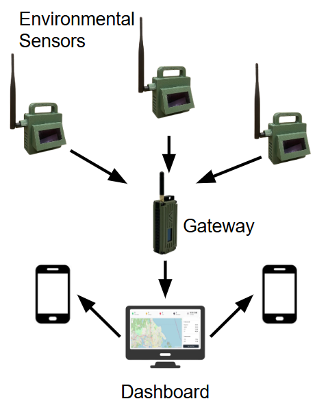
The system is a set of distributed sensor nodes reporting to a central gateway. Each node measures carbon dioxide, volatile organic compounds, temperature and humidity using a BME680 and an SCD40, on a custom PCB with an STM32U5, an SX1262 LoRa transceiver, a lithium-ion battery and solar harvesting, in a 3D printed enclosure shaped to allow airflow over the gas sensors. The gateway runs a weighted additive scoring algorithm that classifies each reading as Normal, Warning or Danger, and a web dashboard shows current values, history, node status and data export. Estimated component cost is about $100 per node.
My part was the power system. The question was whether a node could run unattended through a stretch of poor solar charging. I built a behavioural circuit model in LTspice to estimate battery life and charge current, which put autonomous operation at roughly 16 days. To get there the MCU duty cycle had to come down. A timer-interrupt sleep and wake scheme cut consumption by a further 10.2%, measured on a Nordic power profiler. We measured reliable LoRa communication at 300 m through an obstructed campus. The link budget says the 1 km design target is reachable with a 30 dB fade margin, but that is a calculation, not a measurement.
The prototype works, but several assumptions were never tested. The harvester's charge current was never experimentally validated, only simulated. The enclosure has no formal ingress protection rating. Fire detection was demonstrated at up to 10 m against small controlled burns, because that is what the regulations allowed. A simulated power budget is not the same as a measured one, and the 16 day figure is the one I would want confirmed on a bench before anyone deployed this. The project took first place in both a poster-based research exposition and the capstone design showcase, where it won the Kelly Manning Award.
Final report: Environmental Sensor Network for Wildfire Detection. Open the PDF (55 pages).
Pictures (9)
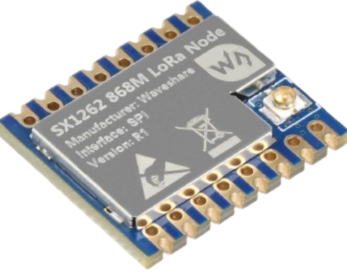 The SX1262 LoRa module.
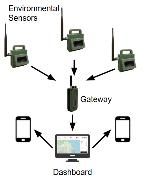 System architecture. Sensor nodes, gateway, dashboard.
 LTspice simulated charge current over 2 days.
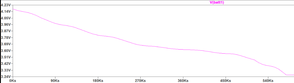 LTspice simulated battery voltage over time.
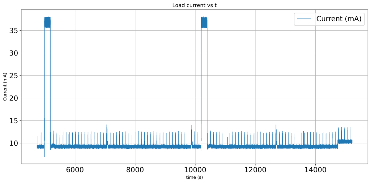 Node load current measured on the power profiler.
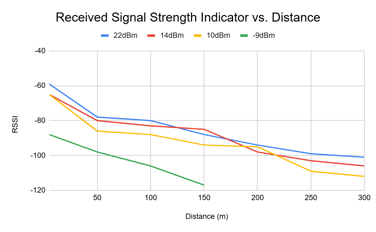 RSSI against distance at four transmit powers.
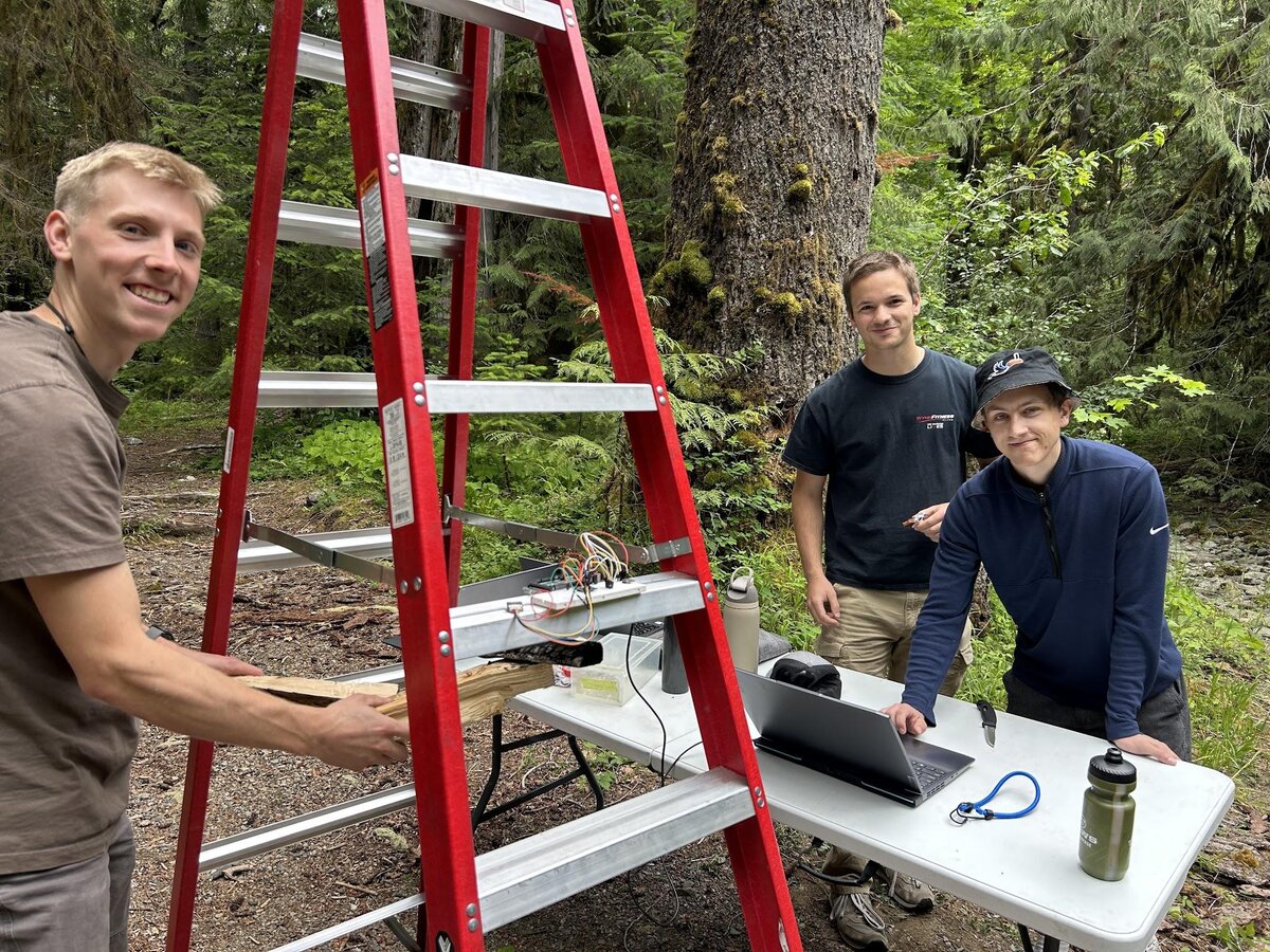 Field testing in the forest.
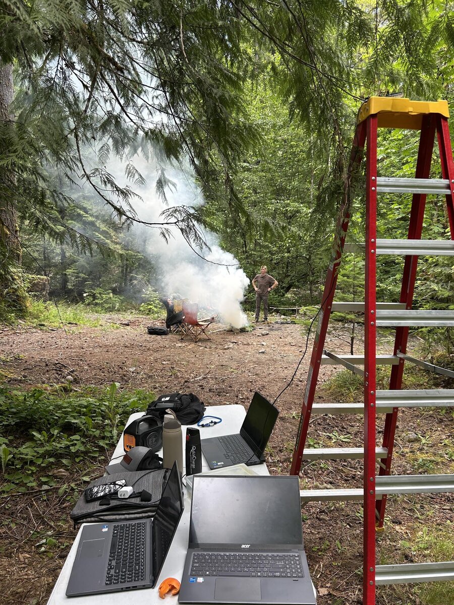 A controlled burn during field testing.
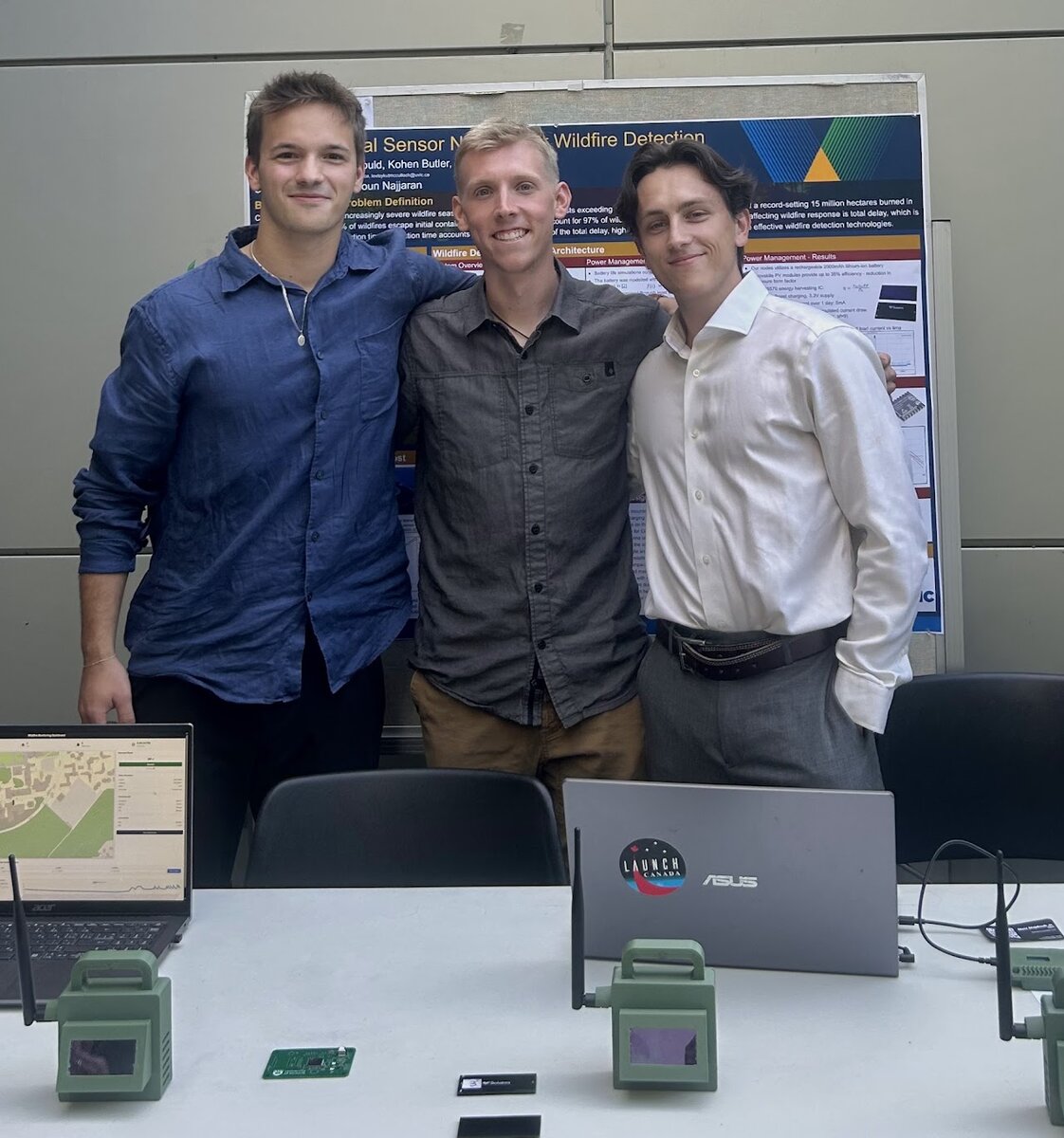 At the research symposium.
C, ARM NEON intrinsics, fixed-point DSP
A fixed-point lowpass digital filter for the ARM Cortex-A7, written in C and optimized for speed.
The objective was to isolate the resonant frequency of a cantilever beam from accelerometer data, with no hardware floating point worth using. The beam resonates at 157 Hz and everything above it is noise, so the filter had to preserve that peak while attenuating the rest, in fixed-point arithmetic, fast enough to be useful. We implemented both an FIR and an IIR so their numerical behaviour, computational cost and optimization headroom could be compared against the same reference.
From the beam's measured response we specified a 4th order Butterworth low-pass with a 500 Hz cutoff and 30 dB stopband attenuation at 1.5 kHz, designed as an analog prototype and mapped to the digital domain with pre-warping and the bilinear transform. That became a 51-tap FIR and a 4th order IIR. A floating-point FIR served as the common performance reference so every later speedup was measured against the same thing. Each version was then converted to fixed point and optimized in turn with loop unrolling, inline multiply-accumulate, software pipelining and NEON SIMD, and benchmarked over 20,000 samples on an emulated Cortex-A7 at 1.5 GHz using timing, instruction counts, cache behaviour and output plots.
The direct-form IIR was unstable in fixed point. The feedback coefficients are of order 1e-5 and want Q28 scaling, while the input and feedforward coefficients are of order 1 and want Q15. A single multiply-accumulate product therefore needs 43 fractional bits, which overruns a 32-bit accumulator by 11. With a coefficient dynamic range of 112.4 dB, the roundoff error was large enough to make the filter oscillate. Limit cycles appeared at the 500 Hz cutoff, and that peak dominated the 157 Hz resonance the filter was meant to preserve. The fix was to restructure it as cascaded biquads, which compresses the coefficient dynamic range within each section, and to add saturating arithmetic and fixed-point rounding on top.
Optimizing individual arithmetic operations did not help much. Inline MAC instructions managed 3.8x over the floating-point reference, against 5.5x for the plain fixed-point FIR and 9.6x for the direct fixed-point IIR. The larger gains came from register utilization and instruction-level parallelism. Loop unrolling took the biquad IIR to 10.2x, software pipelining to 27.2x, and NEON SIMD to 33.5x. SIMD helps in two ways: the vector register file processes lanes in parallel, and it gives the inner loop enough registers to stop spilling coefficients to memory. On a platform with vector registers, prioritize SIMD. On one without them, prioritize software pipelining.
Final report: High Performance FIR and IIR Filter Implementations for the Arm Cortex-A7. Open the PDF (29 pages).
Pictures (4)
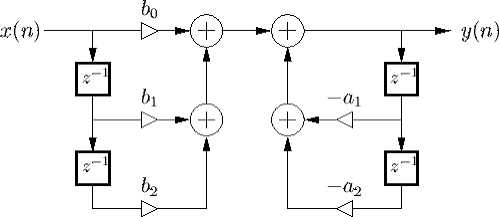
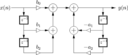 Signal flow graph of a biquad section.
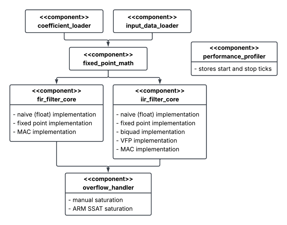 Module breakdown.
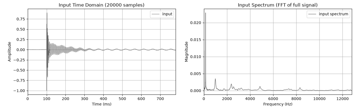 Accelerometer capture.
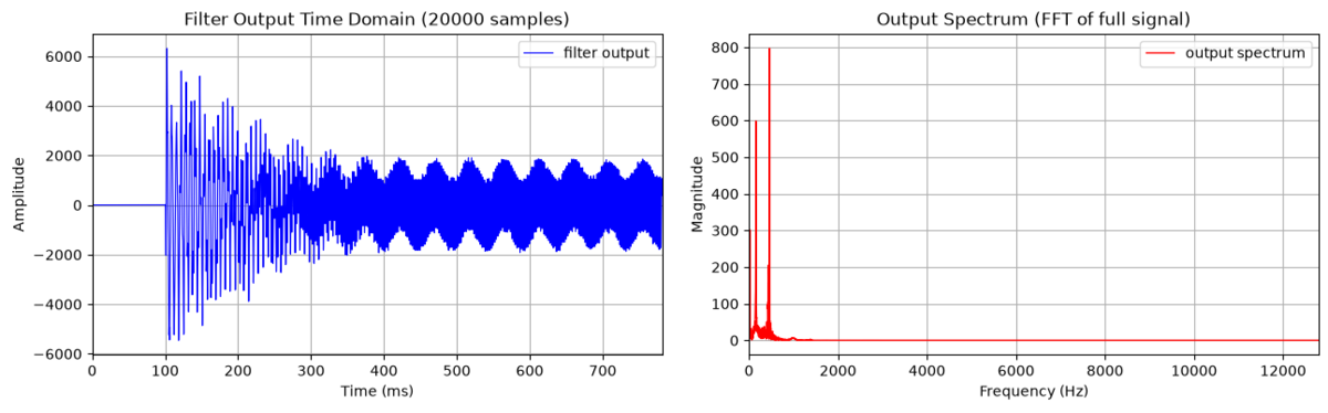 4th order IIR response.
Analog Devices Signal Chain Analyzer, analog design, technical writing
A technical report comparing analog front ends for strain gauge measurement on cost, noise and error.
Commercial strain gauge conditioning hardware is accurate and expensive. The question this report set out to answer was how close a designed-from-parts front end could get for less money. The target was concrete: take a quarter bridge with 350 Ω nominal resistance and ±4 mV full-scale output, amplify it to the 0 to 3.3 V full-scale range of an AD4170-4 24-bit ADC, and hold that amplification across the whole signal bandwidth. The model problem was the DROPBEAR dataset, strain on a vibrating cantilever beam.
I compared four candidate front ends from the literature: a difference amplifier or an instrumentation amplifier, each paired with either a 2-pole RC low-pass or a Sallen-Key filter. Every candidate was modelled in the Analog Devices signal chain analyzer with the sensor and the ADC held constant, so the only thing varying was the conditioning stage. Scoring used a weighted objectives matrix: noise performance at 30%, cost at 25%, accuracy at 20%, complexity at 15% and power consumption at 10%. Cost covered the whole system, including bridge completion resistors, the benchmark ADC, an STM32F4 and PCB manufacturing and assembly.
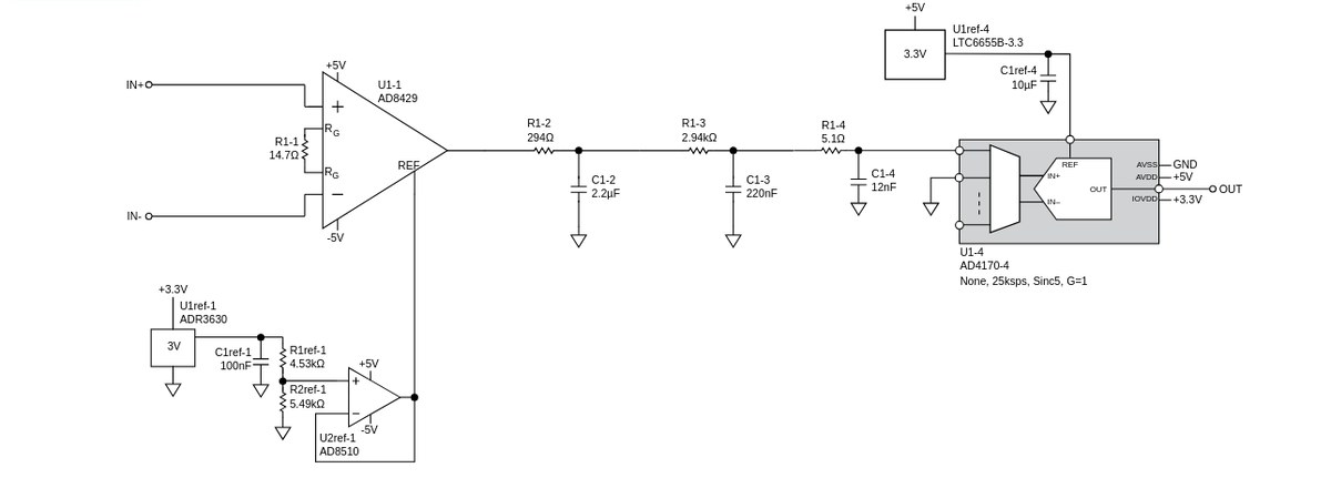
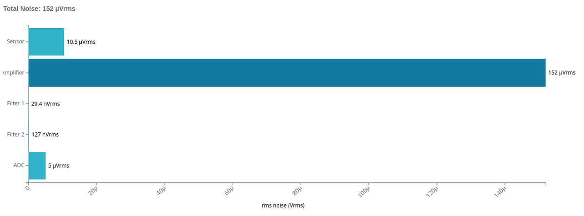
The instrumentation amplifier with a 2-pole RC filter won, at 16.5 µVrms total integrated noise referred to the ADC input, 73.3 mV total offset error, 0.694% total gain error and an estimated $40.93 per input. The weighting is what picks the winner, so it is the part of the method that needs stating. Putting noise at 30% and cost at 25% treats this as a measurement instrument first and a low cost one second. A different weighting gives a different answer from the same simulation data.
The analysis has limits worth stating before anyone uses the numbers. It is op-amp level only, with no transistor-level modelling. It excludes gauge non-linearity, lead-wire resistance variation and supply noise. Filters are capped at second order. A higher order filter would attenuate more above Nyquist. Drift is excluded. Temperature-dependent variation in offset, gain and bias current is left out because no operating temperature range was specified, and choosing one would have biased the comparison. The error and noise totals are therefore underestimates. The design compares well with commercial products on paper, and has not been tested on a bench. The work fed directly into the Anduril 3 DAQ front end.
Final report: Strain Gauge Signal Conditioning System. Open the PDF (42 pages).
Pictures (6)
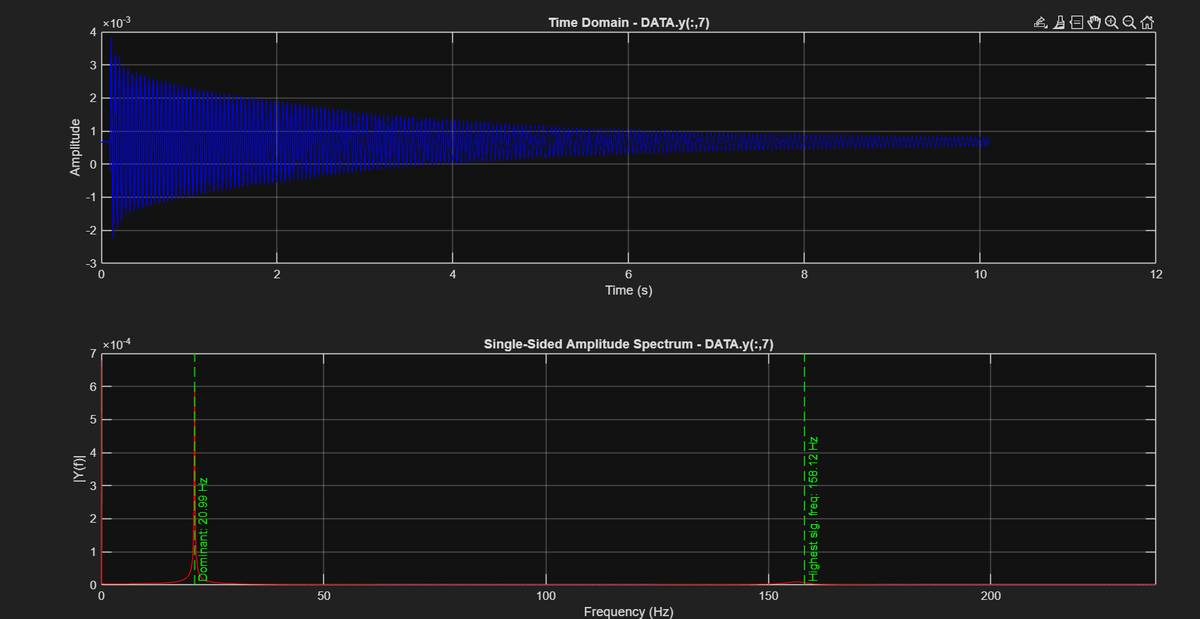 Model strain gauge input signal.
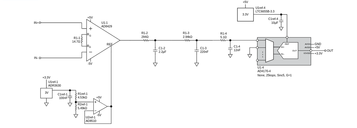 The selected design: instrumentation amplifier with a 2-pole RC filter.
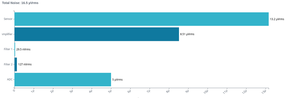 Selected design noise total, 16.5 microvolts rms.
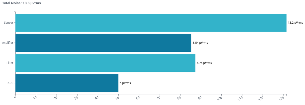 Instrumentation amplifier with Sallen-Key, 18.5 microvolts rms.
 Difference amplifier with RC filter, 192 microvolts rms.
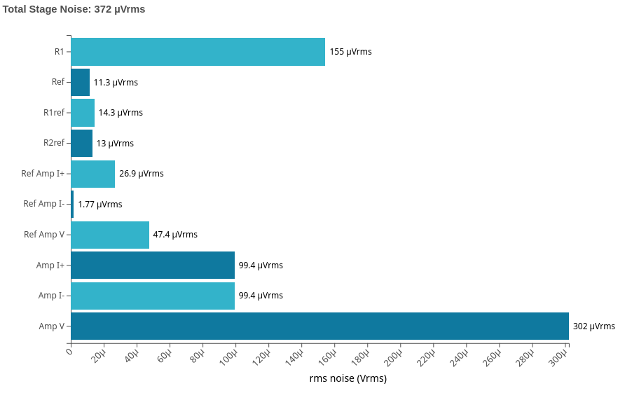 Instrumentation amplifier stage noise breakdown.
SQLite, Python (FastAPI, PDFMiner, Selenium), Vue 3
The interface that drives the bot.
An application that reads supplier invoices and enters their line items into a veterinary clinic's inventory system.
My mom runs a small veterinary clinic, and inventory management was taking too much of her time. Every time the clinic made a purchase, she or an employee had to read each entry on the supplier invoice and type it into inventory by hand. The clinic's practice management software has no publicly available API, and its vendor would not add an integration with the supplier the clinic orders from. With no supported route between the two systems, the work stayed manual.
The system is a pipeline. Invoice PDFs are parsed concurrently with PDFMiner, searching its XML output for the line items. The extracted data is passed to a Selenium bot that navigates the practice management web interface and enters each item on the invoice into inventory. A Vue 3 front end sits on top so the bot can be controlled while it runs, and a SQLite database holds data the user has supplied before so it does not have to be asked for again. The bot runs as a separate process from the API and the two share nothing but Redis. A pub/sub channel carries the answers the user supplies back to the bot, which parks on a blocking listen while it waits, and the bot writes its current activity to a key with a short expiry so the front end can show what it is doing. Those status writes are best effort, so a Redis hiccup cannot take down an invoice run.
The bot has to log into the practice management system by itself, so valid credentials have to be stored somewhere, but nobody using the app should be able to read them. They are encrypted with Fernet into a credentials file, and the key is kept outside the repository in an untracked environment file, so a copy of the source is useless on its own. A setup script takes the credentials without echoing them and backs up the previous file before replacing it. Access to the app is a form login: the submitted password is compared in constant time, and a successful login sets a signed, httpOnly session cookie that expires after an hour and is required by every API route. The whole thing is self-hosted on a Raspberry Pi at the clinic and reached through a Cloudflare tunnel, which serves it over HTTPS without opening a port on the clinic's network or needing a static IP.
An important design decision was to keep a human in the loop. The bot does not run unattended. When it needs information it does not have, such as an item with no matching inventory entry, it stops and asks the user for it. Every critical action waits for human input, including posting the invoice. The process can also be cancelled at any stage. Cancelling undoes the work done by the current execution cycle and reverts the changes it made to the SQLite database, so an interrupted run does not leave the clinic's inventory or the stored data in a half-finished state.
What I took from this project was the importance of understanding the end user. Most of the iterations were not about the parsing or the automation. They were about making the system more interpretable and easier to use: showing what the bot is doing at each step, making clear what it needs from the user and why, and making the state of a run obvious at a glance.
Pictures (1)
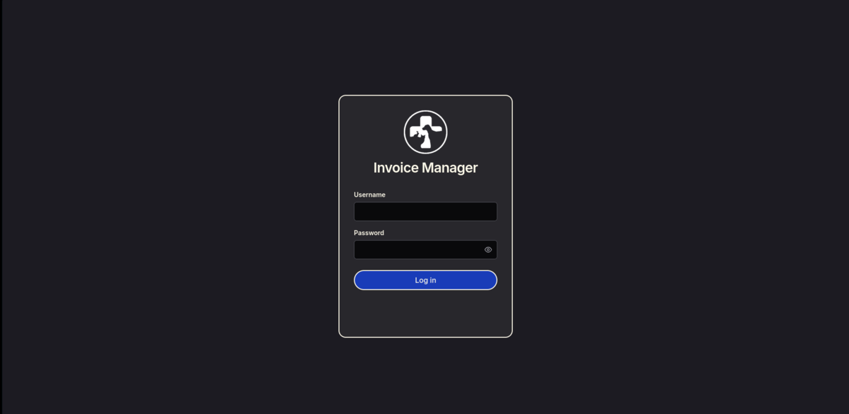 The login screen.
C++, SFML, GLSL
Demo: gameplay and the level editor. Watch on YouTube.
An RPG in C++ and SFML, with a level editor that ships with the game.
You explore a tile map, fight enemies and level up, with a GLSL shader pass handling the lighting.
The game leans heavily on the object-oriented side of C++. It has a custom collision system, enemy combat and player levelling, and a level editor that ships with the game.
The level editor handles the full tile map including which tiles are solid and which render above the player, so you can walk behind scenery. Building the editor as a first-class part of the game meant the content and the engine could be worked on independently.
Object-oriented design earned its keep here. Entities, tiles, the collision system and the UI are separate types with their own state and behaviour, which is what let me add enemy combat and player levelling later without disturbing the parts that already worked, and what let the level editor reuse the same tile and map classes the game renders from. The limitation is the build. There is no build system: the repository carries a Visual Studio solution and project file, so compiling it means opening it in Visual Studio on Windows with SFML linked by hand. That makes it awkward for anyone else to build or share, and it is the first thing I would fix. Moving to CMake would let it configure and build on Linux and macOS as well, and would make the dependencies explicit instead of buried in project settings.
A shorter gameplay clip.
Pictures (3)
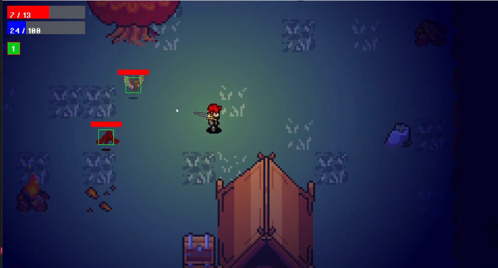
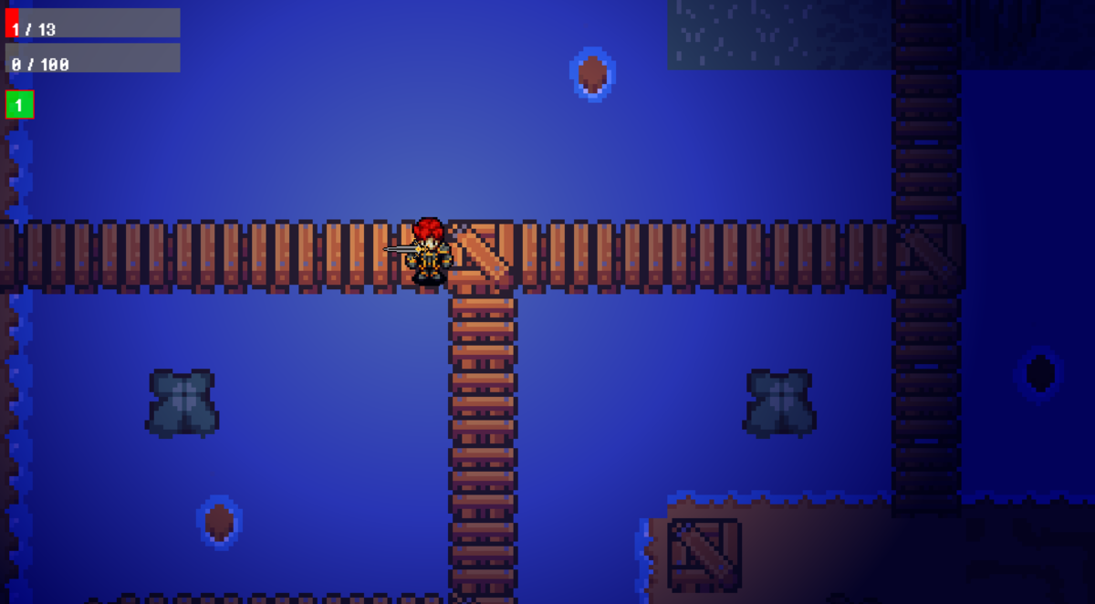 Exploring a level.
 Combat near the gate.
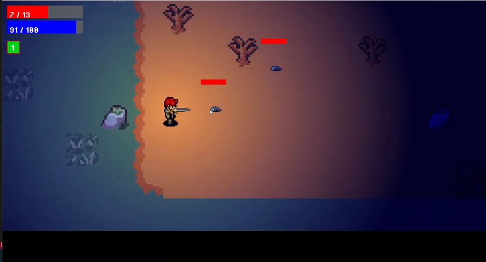 The lighting shader around the player.
KiCad, Arduino, C++, Onshape, Git
UVicRocketry/A2AV-1-CAMERA_PCB-
Flight footage from the camera.
A camera system for UVic Rocketry's Anduril 2 rocket, built to capture in-flight footage.
UVic Rocketry had never recovered usable flight footage. The goal was a camera that survives the flight, starts recording at the right moment without anyone touching it, and comes back with video.
I developed evaluation metrics and researched the options before selecting a camera, then modelled the mounting enclosure in Onshape and designed a custom PCB to carry it. The board has board-mount battery holders, a buck-converter power supply, an Arduino Nano and an accelerometer. The camera only spoke UART, so I wrote a driver for it in C++ and debugged the link with an oscilloscope using protocol decoding.
An important design decision was how to start recording. The camera cannot be started by hand, and battery life rules out recording from the pad, so launch is detected from the accelerometer. Raw accelerometer data gives false triggers while the rocket is being handled and moved, so the signal goes through a simple moving average filter first. That made launch detection reliable enough to use on the pad.
This system captured UVic Rocketry's first ever footage of supersonic flight, above 30,000 ft. Testing turned up two failures worth recording. Pulling the SD card while the camera was still recording produced corrupted footage, so the software had to stop recording or cut power before the card was ever removed. The second took longer to pin down. With the Nano's TX line connected to the camera's RX line, the camera would not start recording on power-up: it showed a steady blue LED and then dropped to a dim orange one. Disconnecting TX and power cycling made it record normally, which pointed at the Nano putting a spurious signal on the line while its own supply came up and leaving the camera's UART in a bad state. A serial line is not idle just because nothing has deliberately been sent on it, and what a line does during power sequencing is part of the interface.
Pictures (5)
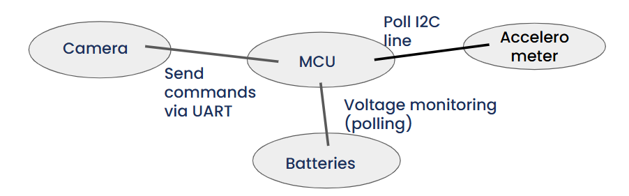 System block diagram.
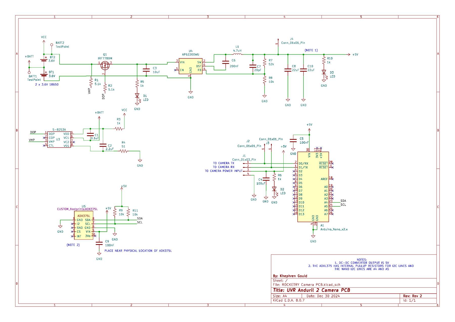 The camera PCB schematic.
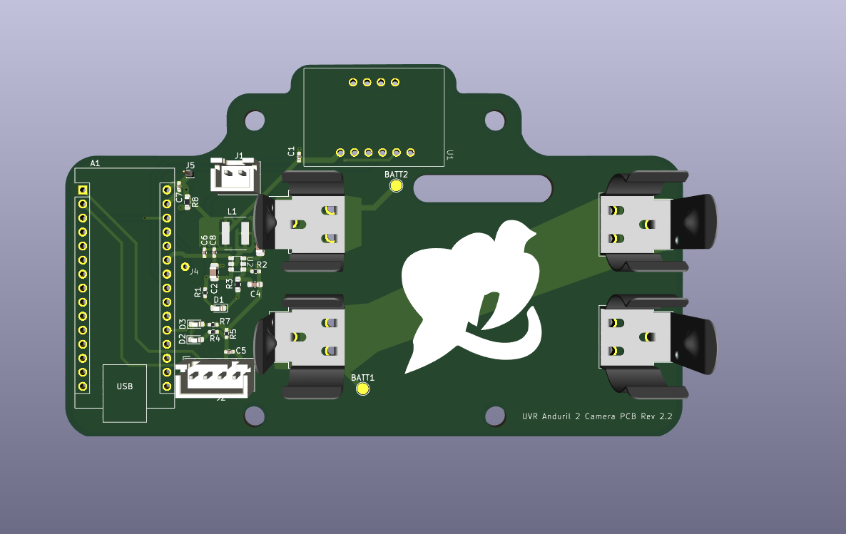 3D render of the board.
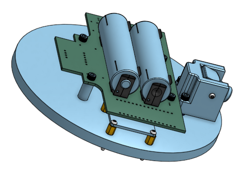 The PCB, batteries and camera mount on the bulkhead.
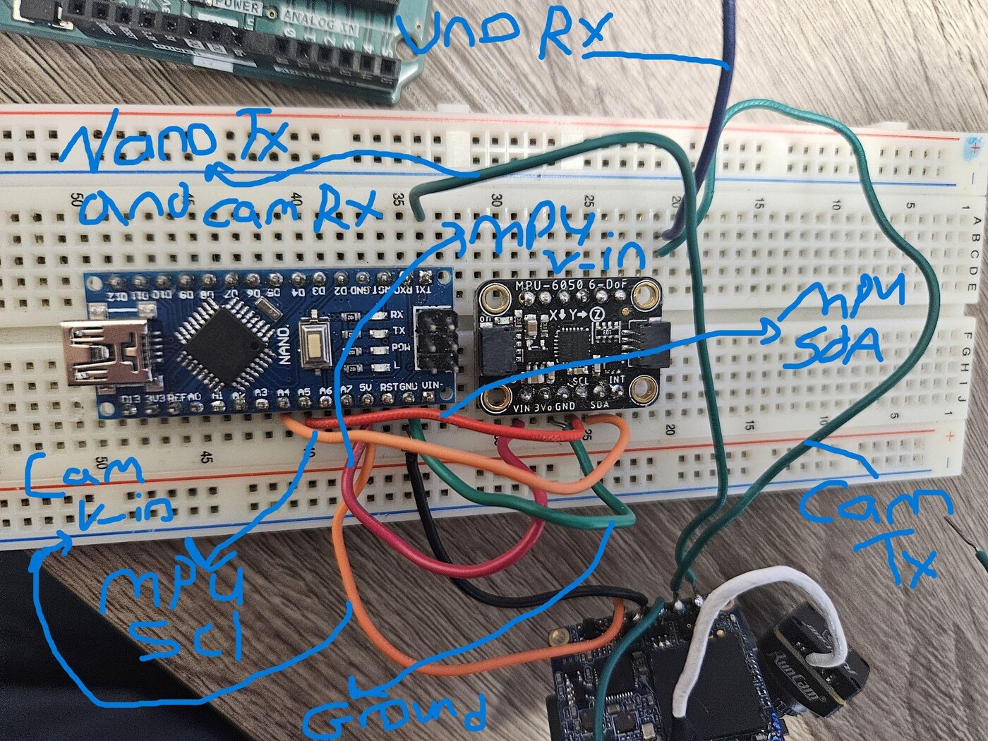 Breadboard prototype of the UART link.
KiCad, Raspberry Pi Pico, MicroPython
Tuning the radio. Press play for sound.
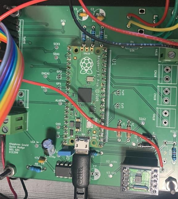
A clock radio with an OLED display, FM receiver, speaker and tuning dial, on a custom Raspberry Pi Pico board.
The requirements were a clock with time setting, format selection and an alarm, plus a radio with channel reception, volume adjustment and channel information on screen. Most of the implementation was fixed in advance. We had to use a Raspberry Pi Pico for processing, MicroPython for the software, SPI to talk to the display and I2C to talk to the radio module, and we had to design and manufacture both a PCB and an enclosure on a "Home Province" theme.
The software is structured around objects: Button, Icon, Radio and Display classes, plus one class for each state the device can be in, being Menu, Clock, Radio, Alarm and Play Alarm. User input arrives through interrupts with debouncing logic and rotary encoder decoding behind it. On the hardware side I drew the schematic and laid out the PCB in KiCad around the Pico, an OLED over SPI and the radio module over I2C. The alarm and the radio share a single speaker through a diode circuit, driven by an LM386-N at a gain of 20, whose gain characteristics I verified on an oscilloscope. The board takes power through the Pico's microUSB input, and the layout puts a 3.3 V plane on the front copper and a ground plane on the back, with 10, 20 and 30 mil traces and the widest of those running from the amplifier output to the speaker to carry the current. The enclosure is a two-piece model in SolidWorks with mounting holes for the board, display, speaker and inputs.
An important design decision was to push interface complexity into software instead of hardware. Because the state machine and display abstraction could carry a real menu, the device did not need a dedicated control for every function, so a lot of buttons and dials came off the parts list. The shared speaker follows the same idea: a small diode circuit lets one speaker carry both the alarm and the radio.
The alarm was unreliable during the demonstration. The alarm trigger time is derived from the current time, but nothing recalculated it when the time zone was changed, so the two could silently disagree. Derived state has to be invalidated when the value it came from changes. Two other things I would change: the amplifier runs at 5 V, and the distortion threshold that sets is what limits the useful volume range, so running it at 9 V would widen it. And the PCB was designed before the enclosure rather than alongside it, which left the board larger than it needed to be and a poor match for the shape it had to sit in.
Final report: Clock Radio. Open the PDF (86 pages).
Pictures (6)
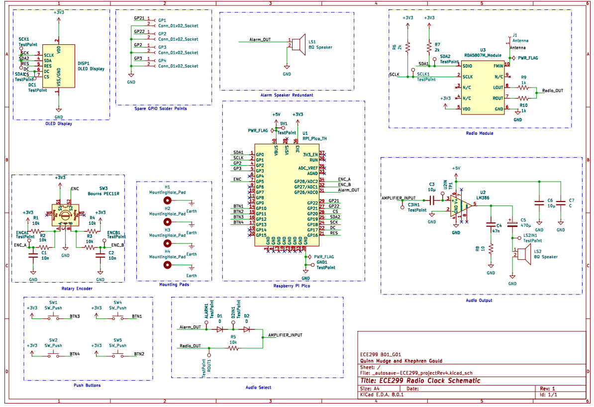 Full circuit schematic.
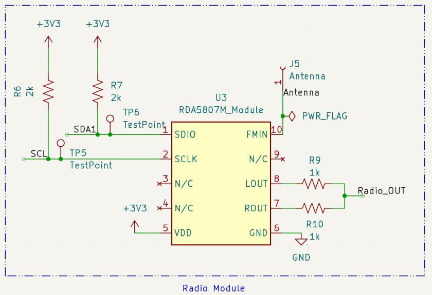 Radio module. RDA5807M over I2C.
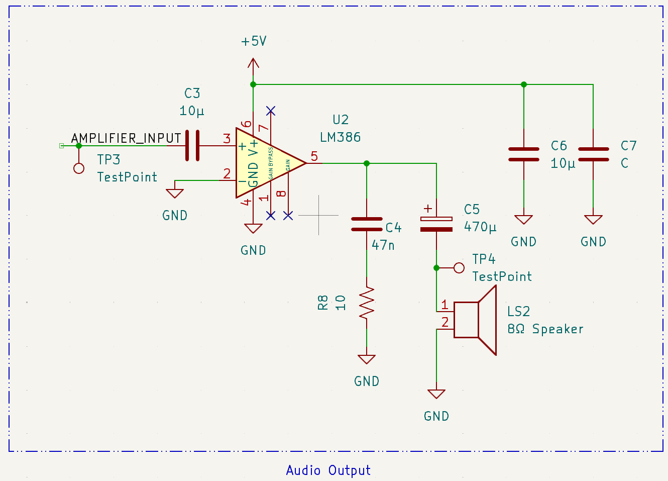 Audio output stage. LM386 at a gain of 20.
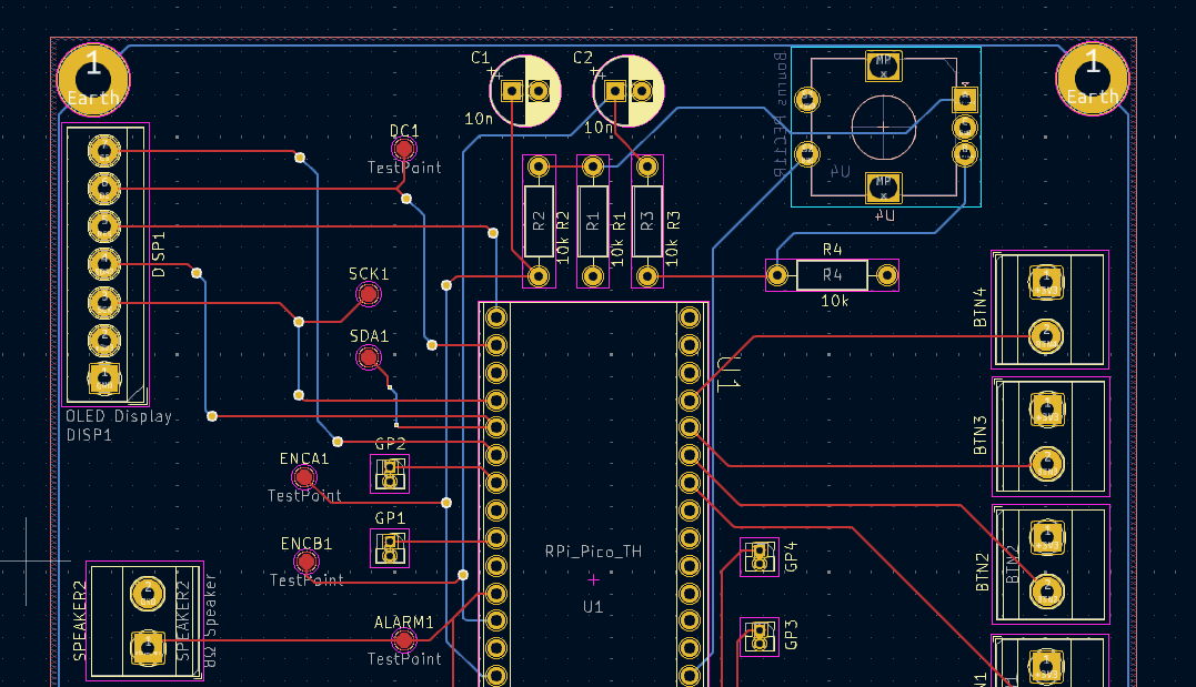 PCB layout in KiCad.
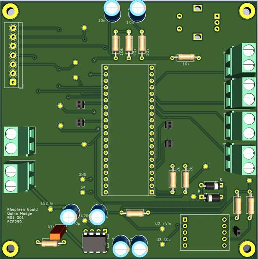 3D render of the board.
 The manufactured board.
RobotC, VEX hardware, sensor fusion, motor control
The robot scanning, approaching and dropping its payload.
A robot that locates an infrared beacon, drives to it and drops an object on it. Built in a team of three.
The robot had to find the beacon on its own, drive to it without running into anything, and release its payload once it arrived. It was never told where the beacon was, and the arena had walls that both blocked the route and looked much like a target to a naive sensor reading.
Everything runs as a state machine in RobotC on VEX hardware. Sensing is an infrared receiver, an ultrasonic range finder, a light sensor, two bumper switches and a quadrature encoder on the right drive motor, with a separate motor for the arm that releases the object. The states cover scanning, confirming the target, approaching, parking, and recovering from a collision, plus a dedicated entry state for starting too close to a wall to scan safely. Scanning happens in two passes: the robot spins one full revolution, measured by the encoder, recording the lowest infrared reading it sees, then spins back and stops once the current reading returns to within about 35 counts of that minimum, which leaves it pointing at the strongest source. The approach is proportional rather than on/off. Inside 40 cm the drive speed scales with the sonar reading and reaches zero at roughly 7 cm, so the robot decelerates into the target instead of stopping dead.
An important design decision was how to tell the beacon apart from a wall. Both read as a bright spot to the light sensor, and the only thing separating them is that the beacon flashes. The robot takes two light samples and compares them, treating a large difference as evidence that the source turned on and off between readings. That only works if the sampling interval is chosen against the flash period. Sampling faster than 50 ms or slower than 100 ms can land both readings on the same phase of the flash, at which point the beacon reads as a constant source, so the interval was set to 70 ms. Getting it wrong does not produce a small error, it produces a robot that drives confidently into a wall.
With three people and a fixed deadline we split the work by what each person was best suited to and held weekly meetings to check progress against the plan. The coordination took more effort than the engineering. On the technical side, almost none of the failures were in the driving or the mechanism. They came from trusting a single sensor reading, and every fix was a form of cross-checking: confirming the beacon by its flash rather than its brightness, keeping the bumpers as a backstop for whatever the sonar missed, and adding a separate startup state for the case where the robot began too close to a wall to scan at all.
Pictures (1)
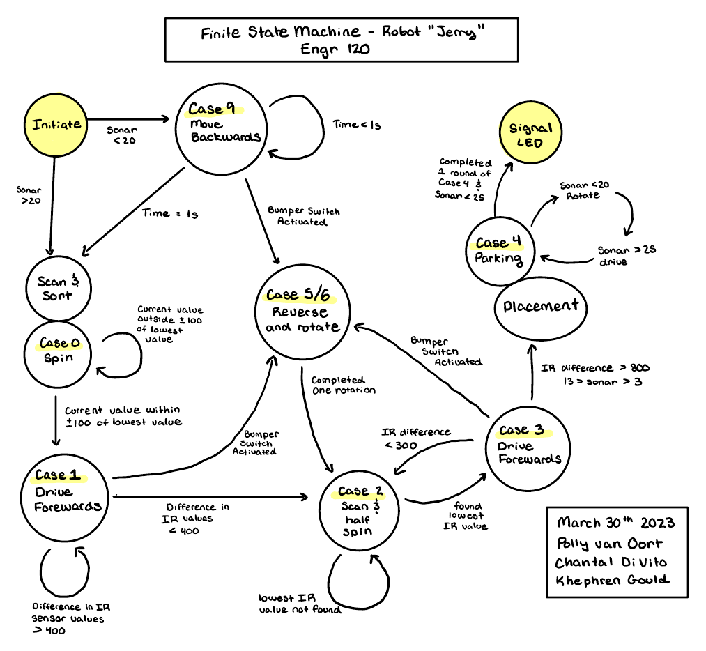 The state machine the robot runs.
Digital systems design in VHDL on a Xilinx FPGA.
Driving a VGA display from the FPGA, capturing frames from a digital camera into a BRAM frame buffer, converting RGB to greyscale, and running a Sobel edge detector at video rate. The sync generator divides a 25 MHz pixel clock with an 0 to 800 counter for horizontal sync at 31.3 kHz, and that signal drives a second 0 to 525 counter for vertical sync at 59.3 Hz. Getting the filter into hardware is what lets it keep up with the frame rate.
Lab 3 report. Open the PDF (5 pages).
Pictures (7)
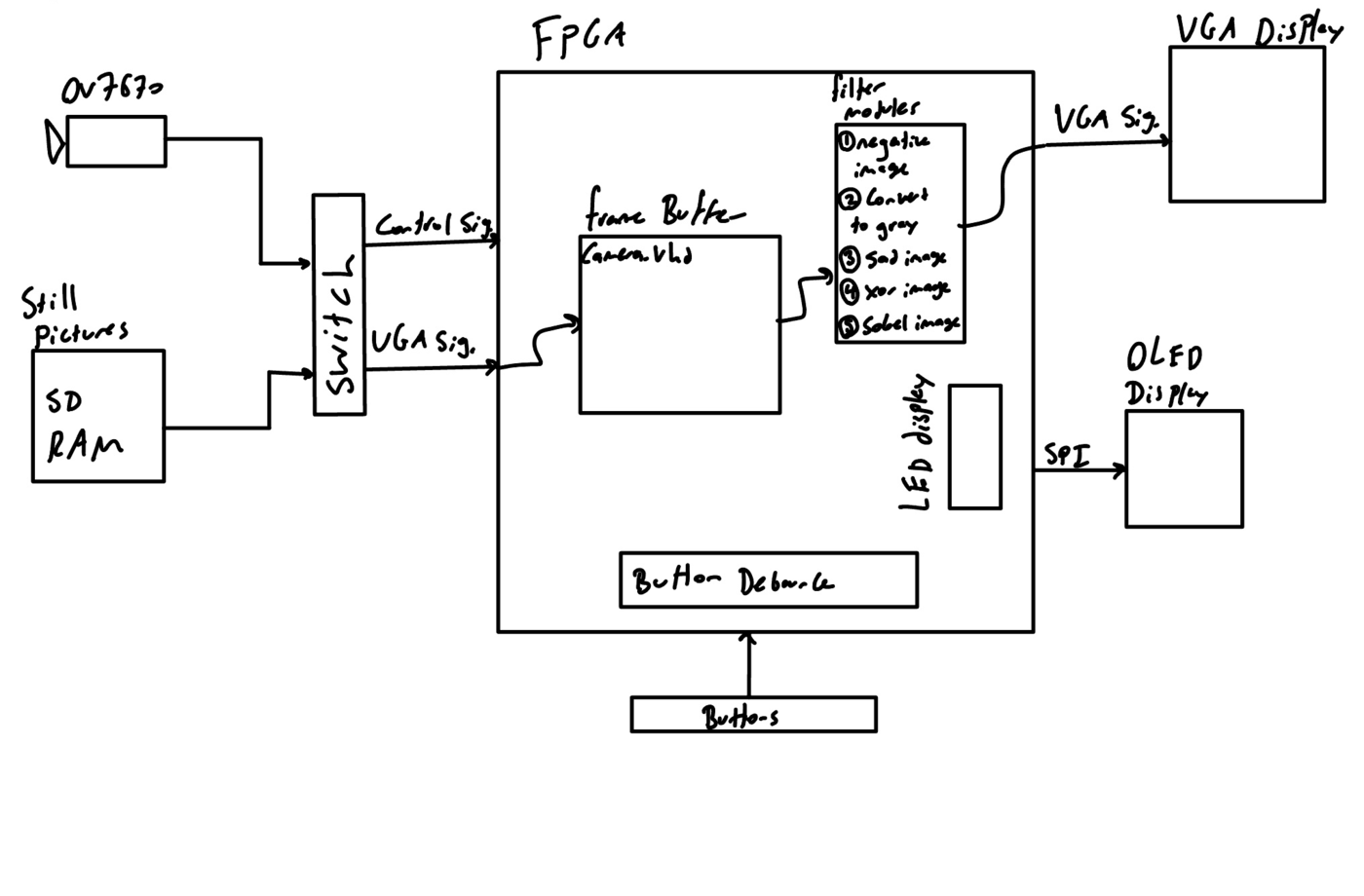 The video pipeline, sketched out.
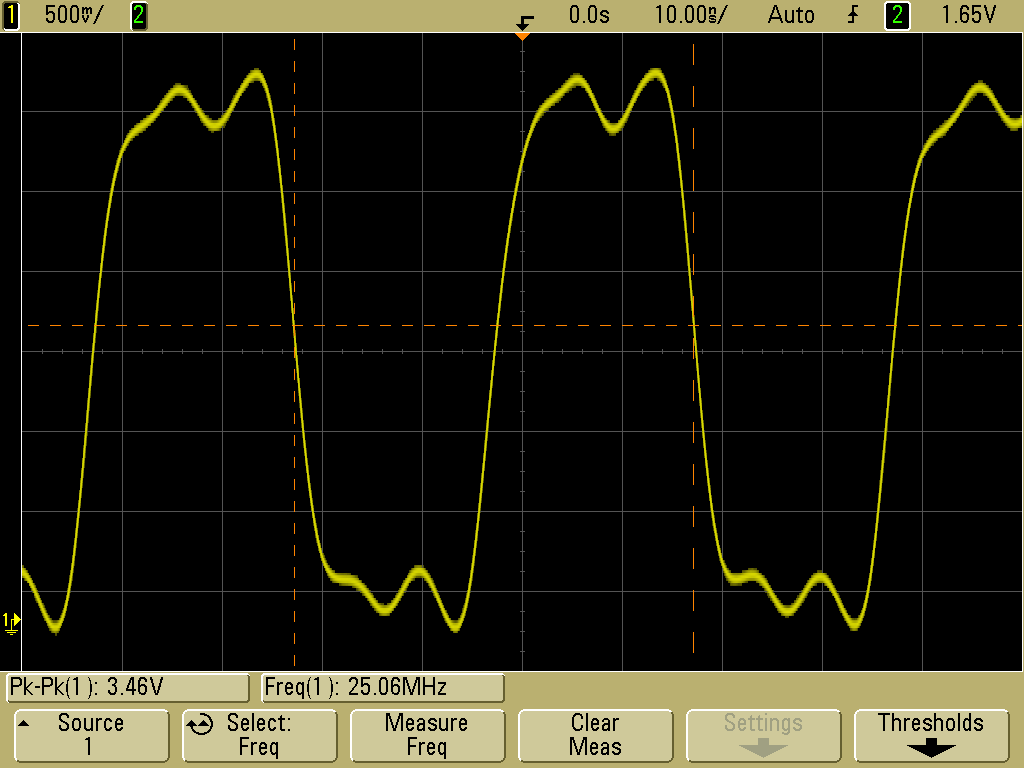 The 25 MHz VGA pixel clock.
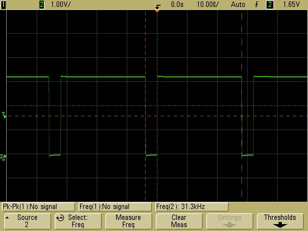 Horizontal sync at 31.3 kHz.
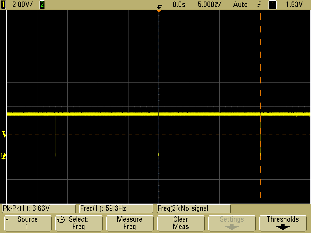 Vertical sync at 59.3 Hz.
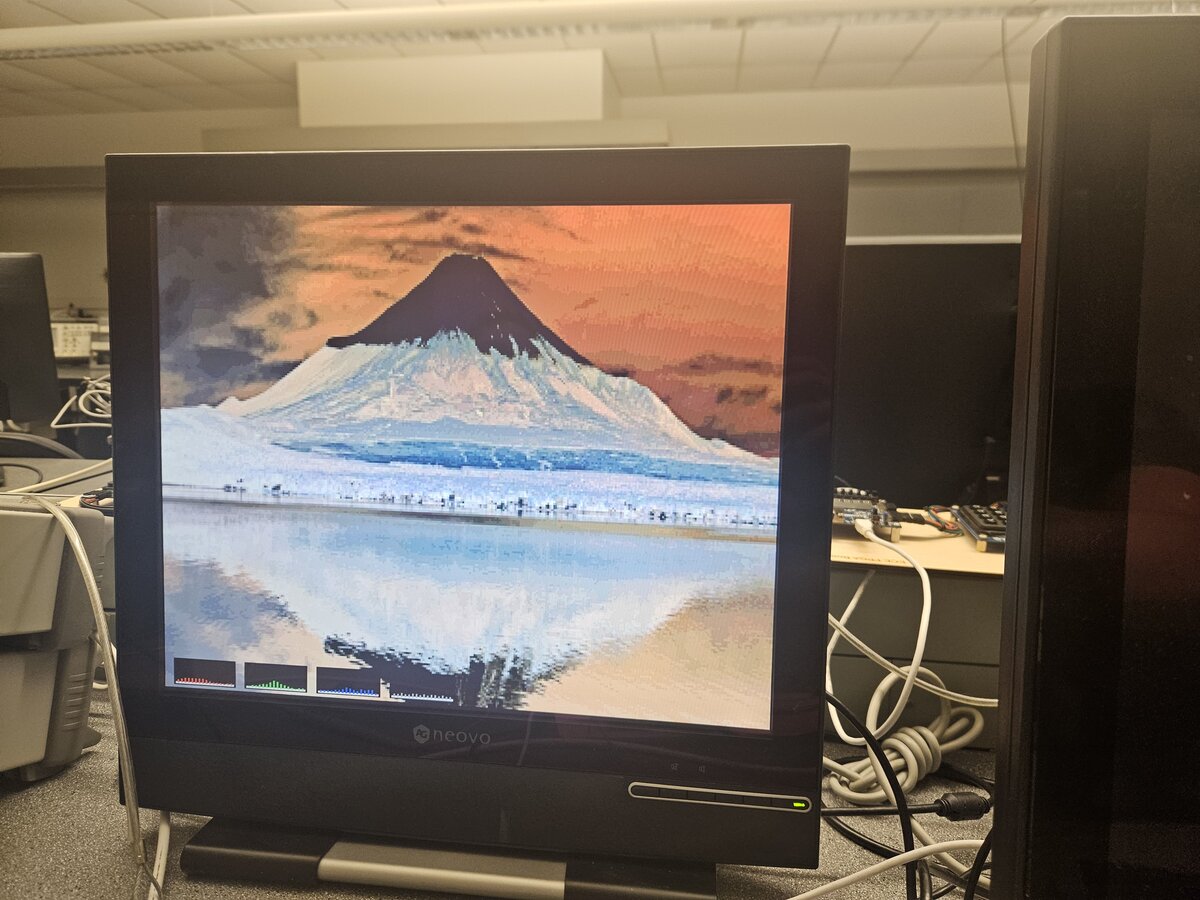 Camera output on the VGA display.
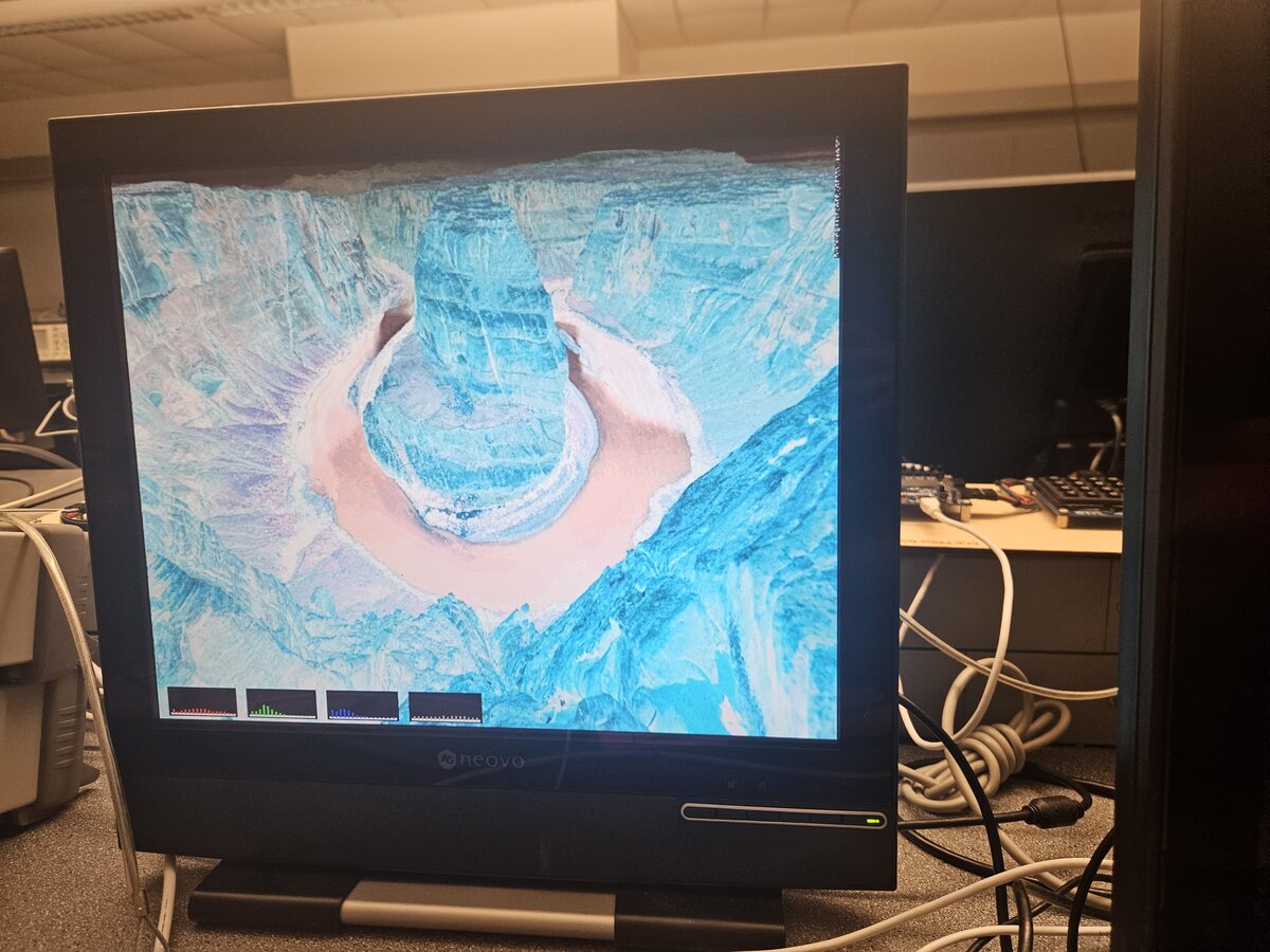 The same frame after processing.
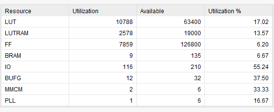 FPGA resource utilization.
Instantiated a MicroBlaze processor on the fabric and grew a system around it: AXI UART for console output, AXI GPIO to read the switches and drive the LEDs, and then a custom IP block of my own added to the bus. Debugged a binary counter on real hardware with an integrated logic analyzer, which is the part worth knowing, since it is how you see inside a design once it is no longer in simulation.
Lab 4 report. Open the PDF (5 pages).
Pictures (6)
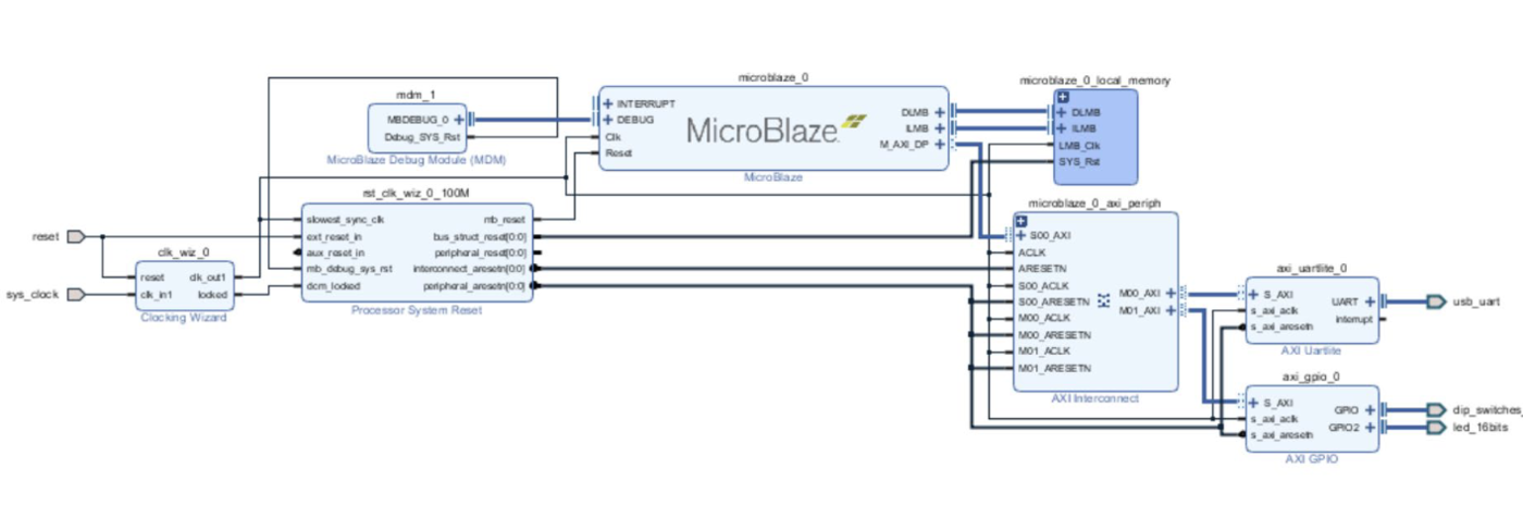 The MicroBlaze system on the AXI bus.
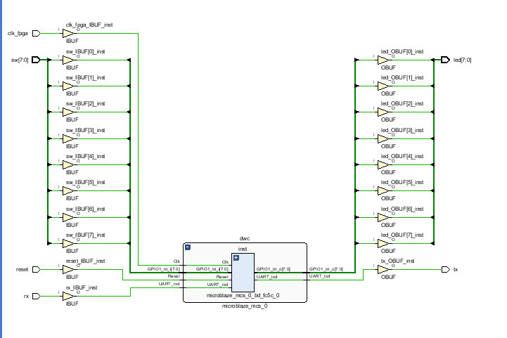 Generated schematic for the block design.
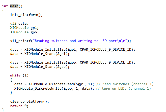 Reading the switches and driving the LEDs.
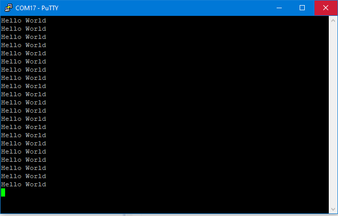 Console output over AXI UART.
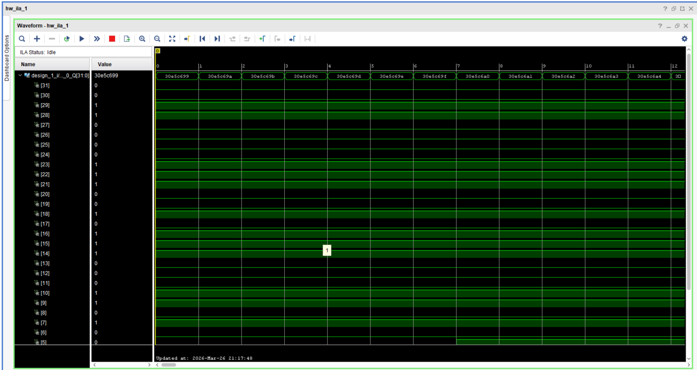 Integrated logic analyzer capture.
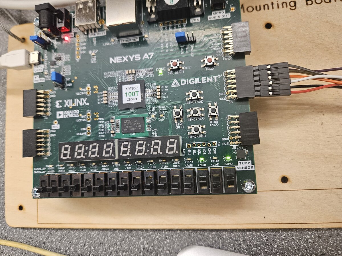 The Nexys A7 running the design.
Real-time systems with FreeRTOS on an STM32F4 Discovery board.
A traffic intersection simulated in FreeRTOS. A software timer runs the light state machine, three shift registers drive the rows of LEDs standing in for the road, and an ADC reads a potentiometer that sets how fast cars arrive. Tasks pass state to each other over queues, with priorities assigned so the light never misses a transition. We drew the board as a KiCad schematic as well.
Project 1 report. Open the PDF (33 pages).
Pictures (1)
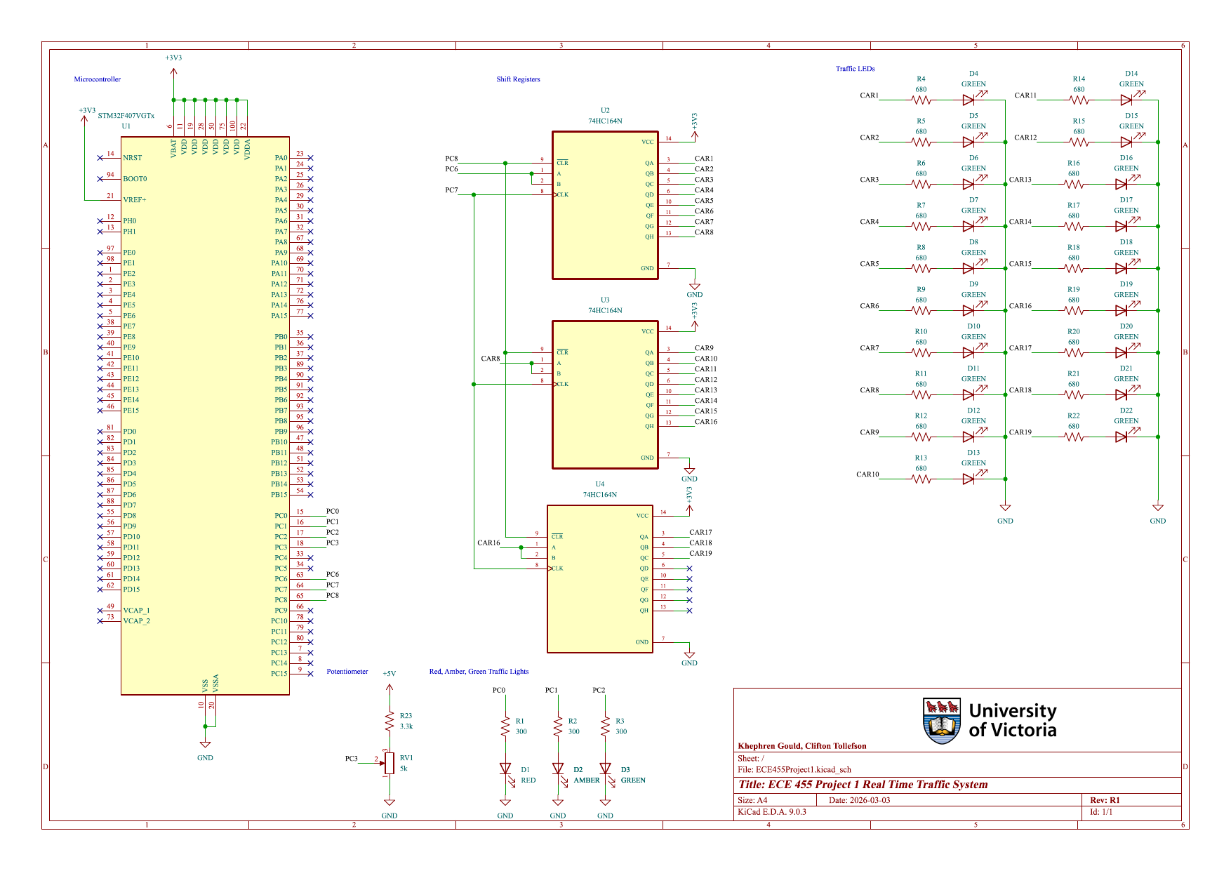 Schematic. STM32, three shift registers, and the LED rows standing in for the road.
An earliest deadline first scheduler layered on top of FreeRTOS. Each task is recorded as a struct holding its type, periodic or aperiodic, along with its id, release time, absolute deadline and completion time, kept in a linked list. A generator task releases work, the scheduler task reorders FreeRTOS priorities so the nearest deadline runs next, and a monitor task reports on the active, completed and overdue lists. Released and completed tasks arrive over separate queues, and a semaphore signals when something has missed its deadline.
Project 2 report. Open the PDF (37 pages).
Pictures (1)
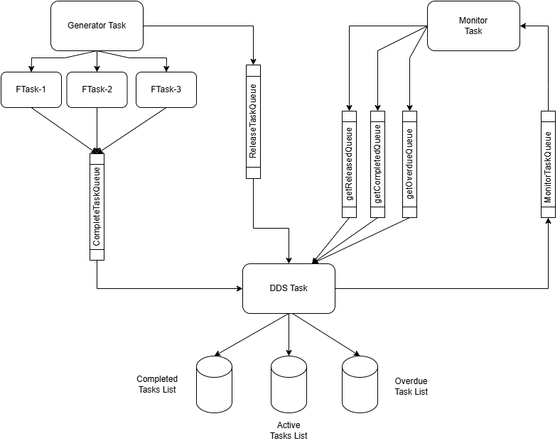 Task and queue layout. The generator releases tasks, the DDS task schedules them, the monitor reports.
These two came before The Wanderer. Both are written in C++ with the SFML library, and the reason for building them was to get enough experience with SFML to attempt something larger.
C++, SFML
A Space Invaders style game. It has separate scenes for the menu, the high score table and gameplay, collision detection, an explosion animation when an enemy is destroyed, and sound effects on firing and impact. Movement is on WASD and shooting is aimed with the mouse. The high score table persists between runs. I drew the health bar and star sprites myself.
Controls: WASD to move, left mouse to shoot, Esc to quit.
C++, SFML
A shooter where you can fire in any direction. Larger enemies split when destroyed, spawning one smaller enemy for each vertex of the parent shape. Collisions use circular bounding boxes, the special ability runs on a cooldown timer, and objects rebound off the window edges. Almost every gameplay parameter is read from a config file rather than compiled in, so the feel of the game can be changed without rebuilding it.
Controls: WASD to move, left mouse to shoot in any direction, Q for the special ability once the on-screen timer reaches 0, P to pause, Esc to quit.
This is where it all began. The Arduino kit was my first introduction to both electronics and programming, and I worked through the tutorials one project at a time. Three of them are below. The sketches are in KhephG1/Arduino.
Arduino, C++ · project11.ino
A pushbutton and a 16x2 character LCD driven over six pins. Press the button and it rolls, then prints the result to the display.
Arduino, C++ · project7.ino
Press play for sound.
Seven buttons wired as a resistor ladder and read through a single analog pin. Each button pulls the divider to a different voltage, and the sketch matches the reading against a range to decide which note to sound on the piezo. The notes run from 262 Hz up to 523 Hz.
Arduino, C++ · Project3.ino
Three photoresistors, one per colour channel, feeding three PWM outputs that drive a red, a green and a blue LED. Shade one sensor and that colour drops out of the mix.